>
QUOTE (antoine64 @ Jan 1, 2016 - 7:26 PM)

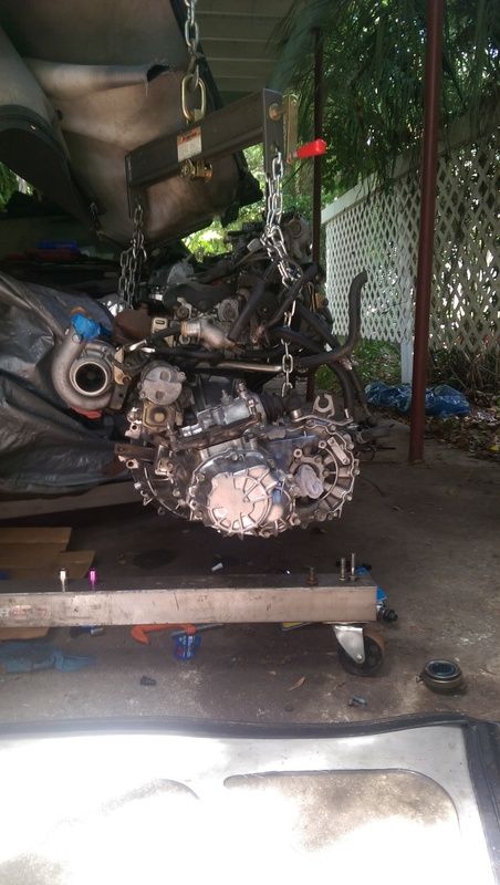
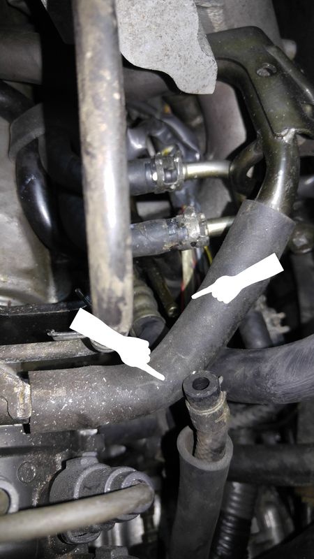
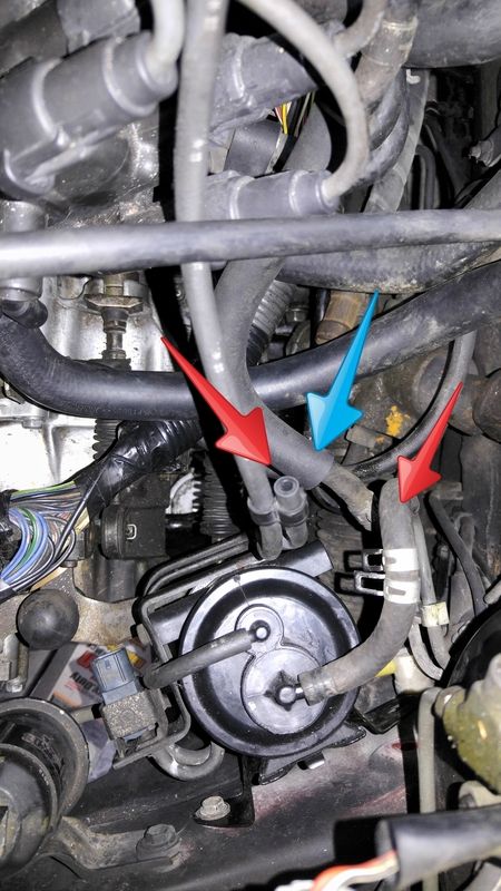
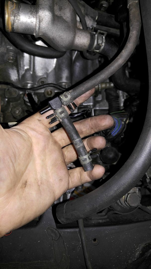
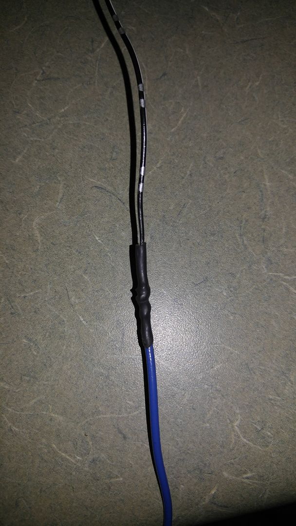
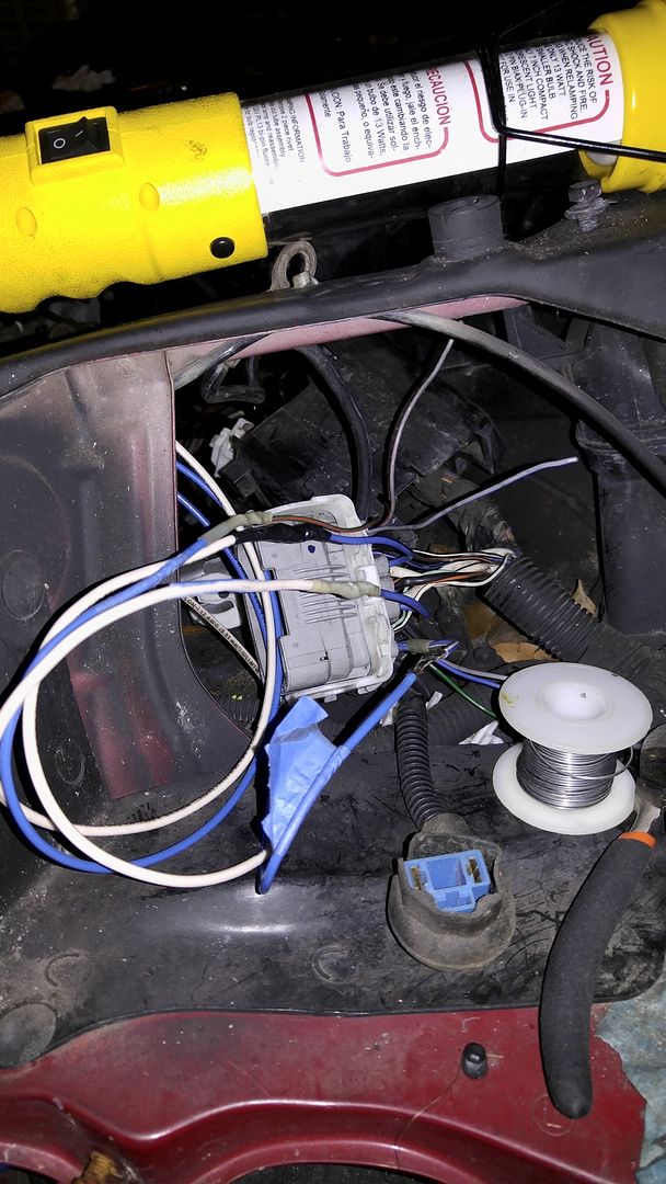
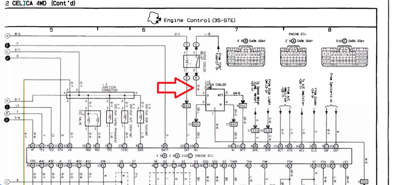
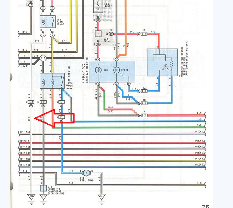
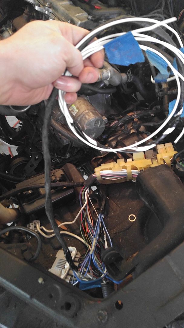
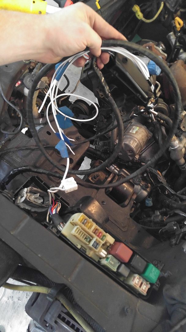
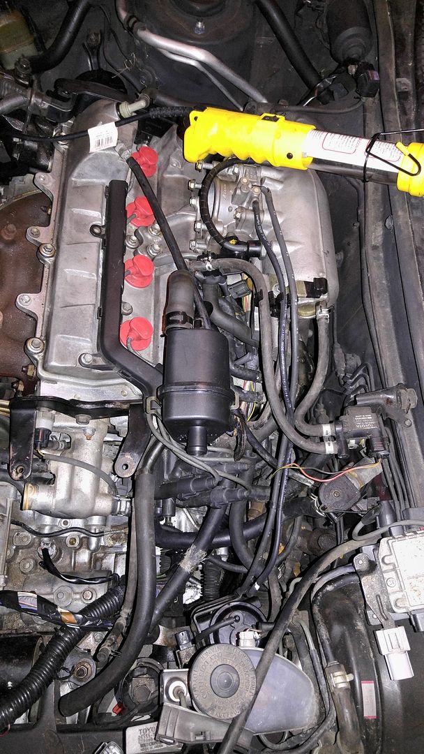
>in your first picture with the white arrows, that is the fuel return line. It connects to the end of the fuel rail on that nipple you point to with the white arrow. I recently had that line leaking fuel so I had to replace it. You might want to get a new hose while you've got things apart to avoid smelling gas. your red arrows image sounds correct. I think you want this hose to go to P or E on the throttle body providing vacuum when the throttle is open but no vacuum at idle. on the last picture those look like vacuum hoses but without seeing where the other end goes, I can't tell.
On that fuel return line, I assume that goes back to the tank? I thought it would be connected to charcoal canister? Or does the line above it, the right right arrow do the canister to tank run?
I think it does, but I'm trying to mesh together how all these goes looking at 50x diagrams, and it seems most have just deleted this. Seeing I already have, I figured I'd hook it up =P
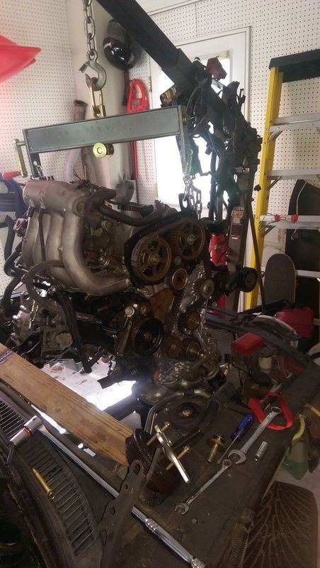
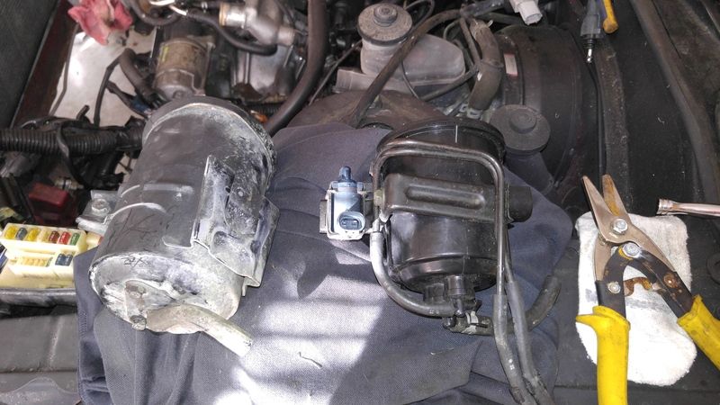
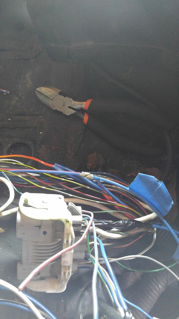
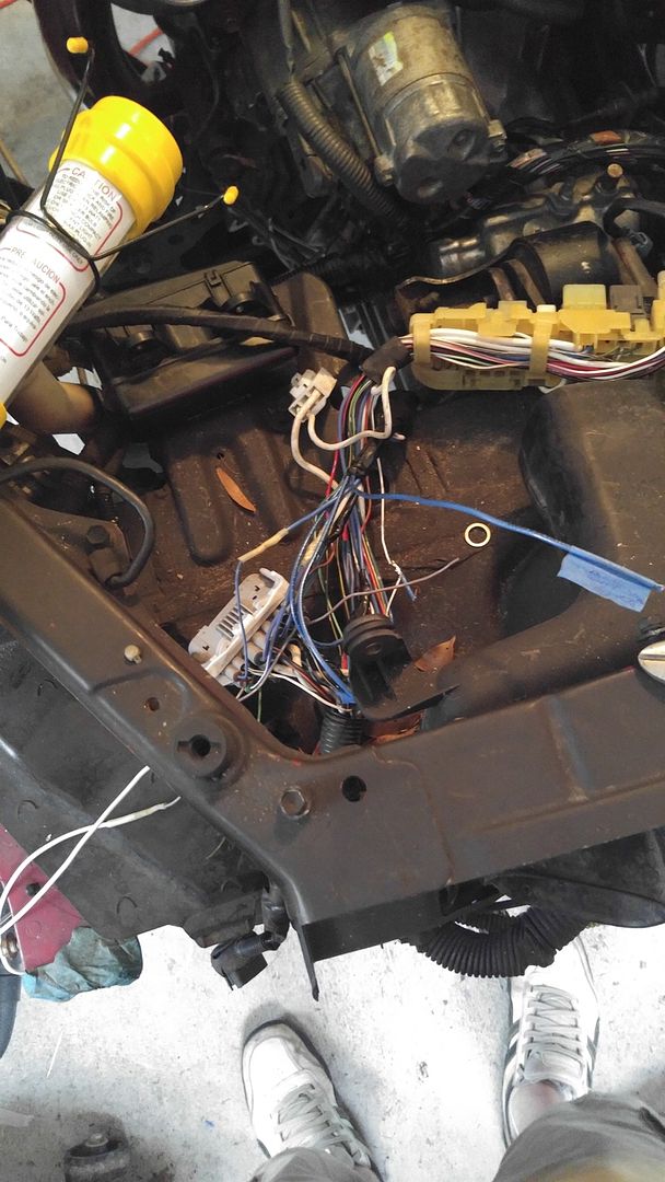
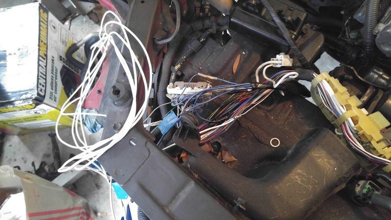
On that last picture, those small hoses connect to a hardline that ends up to another soft line on the intake manifold.
Did find my MAP sensor, so that will cover one of the inlets on the intake, and VSV which did relieve some confusion. Appears one end of the VSV goes to the intake, the other to the W2A exchanger.
Appreciate all the help!
The most pictures I could find on it, where on Pressure2's build, but he removed his canister, but it did help me figure out other lines lol.
I may have some of it figured out. Go go part numbers...
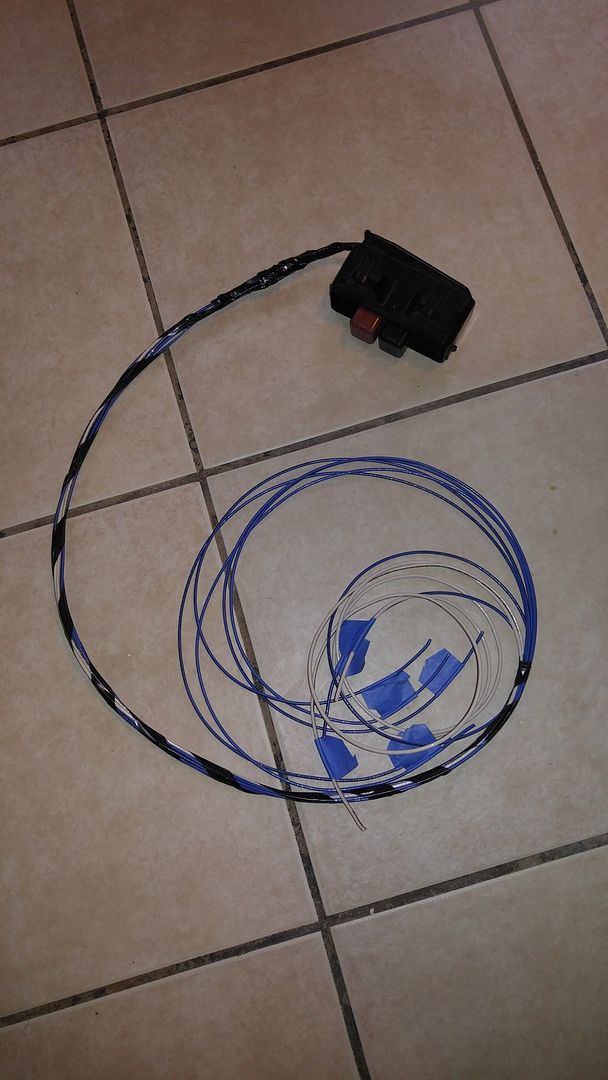
77277A - Fuel Return Tube - Indicates the return to the middle hardline
77261E - Tank to Canister - Indicates the left most line facing forward of vehicle.
----
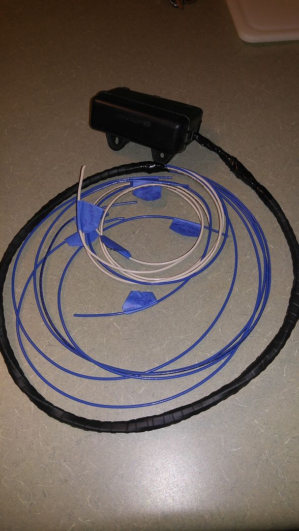
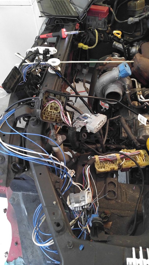
Well just went to it, and got more done...I think I have it all right now...Had to go pick up a small line and bridge to replace what seems to be gone. Luckily they had it available =) Just the line that comes from the charcoal to those nipples on top labeled P & E
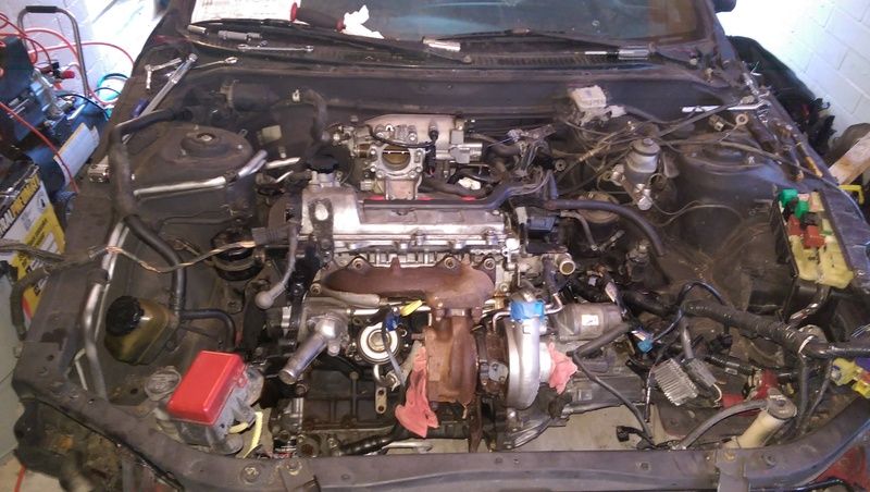
Confirmed I got the right fuel return to hardline hooked up, found my VSV, and turns out I have 2 MAP sensors.
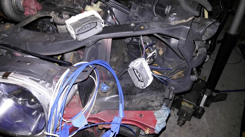
I didn't realize it was still attached to the harness this whole time. First thing I did when I got the engine was remove the harness expecting to ship it off. Didn't work out. It would appear the bracket and the top piece of it with part number were torn off but the sensor and line itself were intake and connected to the manifold, I just removed the connection. So, I have a spare now =)
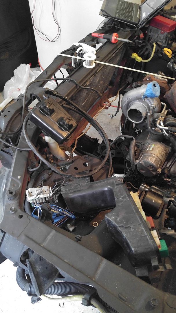
Looks dirty as hell, but meh, at least things are finally lining up.
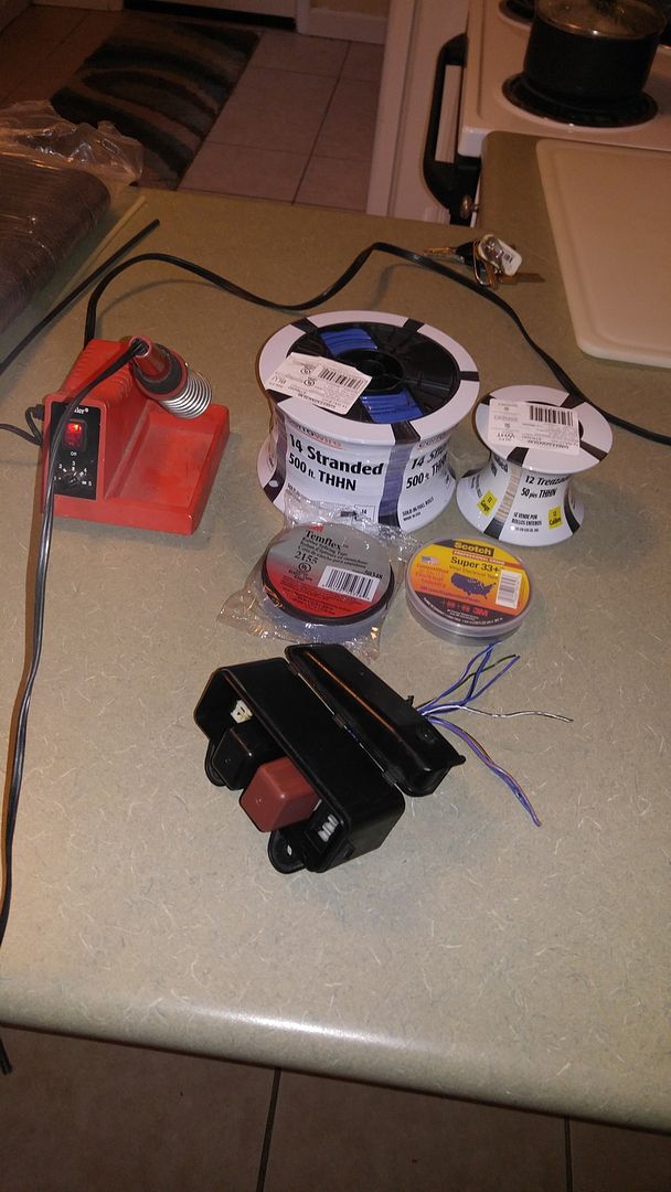
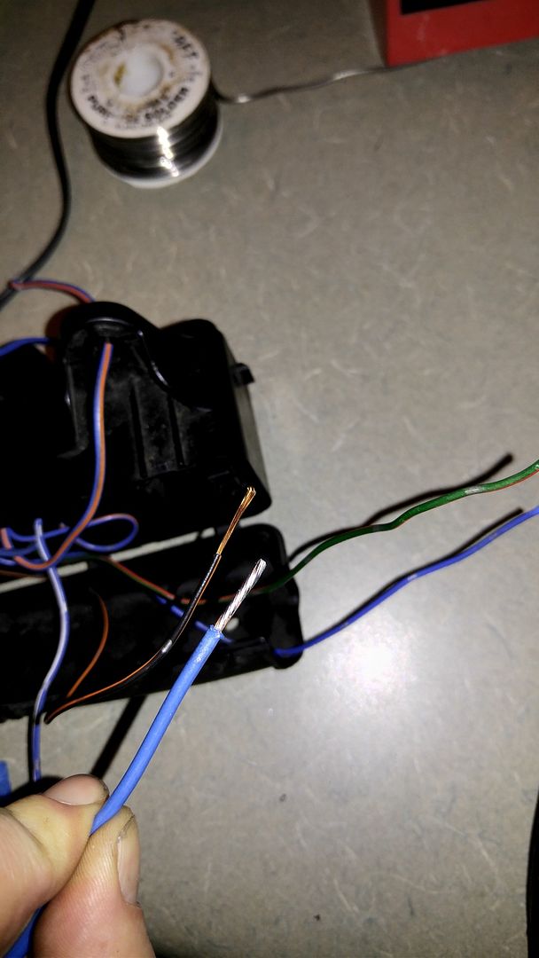
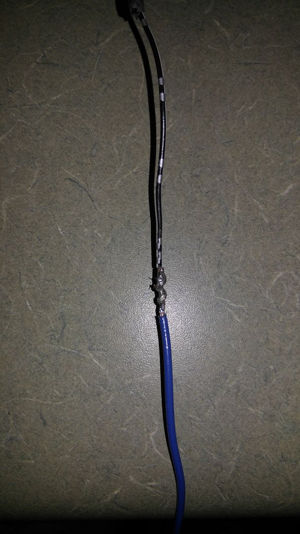
I expect to do wiring tomorrow. Unpin, repin, fight if I want to extend just a few wires or get creative...
Oh anyone know why the coil pack is hitting the hardline on the master? I swear I have the right mounting place...
This post has been edited by rave2n: Jan 2, 2016 - 5:01 PM