here's a mini write up from CW racing after various simulations from everyone's input.
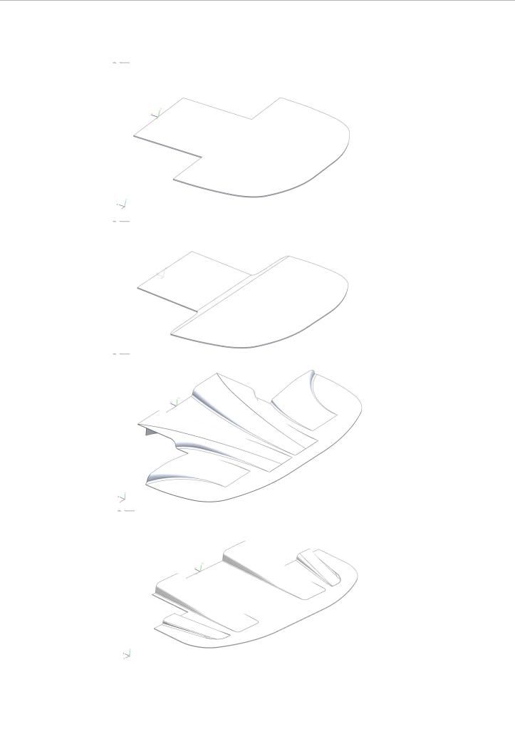
Design 1. simply a flat plate. Produced
some down force. Would be the most easy
to produce and fit.
Design
Design 2. similar to design 1 but with an
angled tail. Produced approximately 2x the
down force of design 1 and with the benefit
of drag being reduced by 1/2.
Design 3. a very complicated design which
was influenced by comments from members
on forums. The piece would be very
complicated to make and mount due to its
shape. It does however produce over 4x
the down force of design 1. negative point
though is it also produces 3x the drag.
Design 4. a design that id a hybrid of design
1 & 3. not the simplest to make but much
easier than design 3 and should be simpler
to fit. It produces 3x the down force of design
1 and only a fraction more drag.
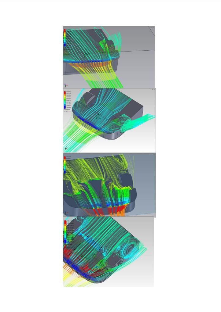
Design 1. CFD shows quite simple flow due to its
simple design. The swirly bit behind the wheel is the
wake from the tyre.
Design 2. bit more going on. More lower pressure
under the car as there is much more blue. Also
selected flow lines through the rotating wheel. You
can see how the wheel pumps the air out like a jet.
Design 3. lots of 3d flow on this one. You can still
see the swirly bit behind the wheel. Also areas
where the flow separates away from the strakes
in the channel. Also an area in front of the tyre.
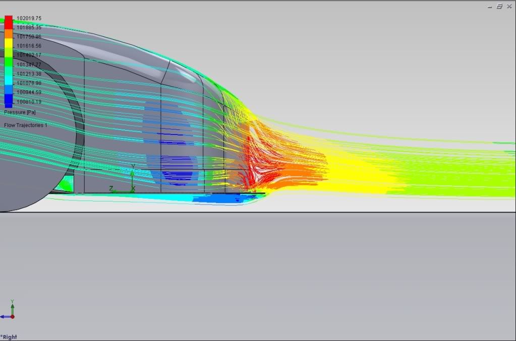
Design 4. Lots more laminar flow. Still with the
wake behind the wheel.

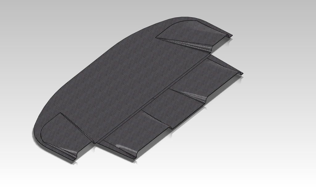
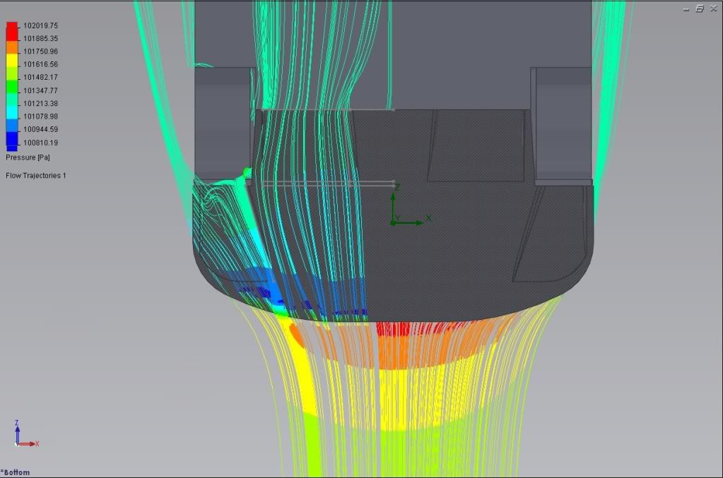

 looks great though.