
Overview
Essential modification for all US Celica owners with JDM projector headlights! JDM projectors are designed for right-hand drive countries with left-side traffic patterns. The beam cutoff shield directs light incorrectly for US roads, causing poor illumination and potential safety issues. This modification corrects the internal cutoff shield to provide proper light distribution for left-hand drive vehicles.
🕒 Time Required: 4-6 hours per pair
💰 Cost: $20-30 (tools and materials)
🔧 Tools: Metal fabrication tools, solvents
🚨 Why This Modification is Essential
- Safety Critical: Unmodified JDM projectors create dangerous dark spots and glare for oncoming traffic
- Legal Compliance: Incorrect beam pattern may not meet DOT requirements for US roadways
- Vision Optimization: Proper cutoff provides better road illumination where you need it most
- Professional Installation: Many shops install JDM projectors without this crucial modification
- Performance Enhancement: Transforms poor lighting into excellent HID performance
Required Tools & Materials
🔧 Disassembly Tools
- Phillips and flat-head screwdrivers
- 10mm and 8mm socket wrenches
- Side cutters
🏭 Fabrication Tools
- Drill with 3mm bit
- Mounted metal grinder
- Sheet metal (1mm thick)
- 12V transformer (testing)
🧪 Cleaning Supplies
- Paint thinner (1 gallon)
- Very large pan for soaking
- Brush for glue removal
- Silicone sealant
Installation Steps
Step 1: Disassemble Headlight Housing
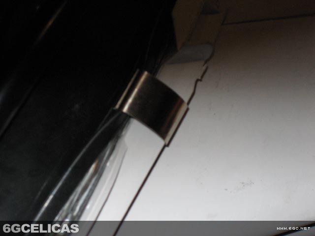
Remove the headlight from packaging or vehicle. The housing is held together by metal clips around the perimeter. Carefully bend these clips outward using a flat screwdriver - lift the plastic side first to avoid damaging the glass. Remove the black rubber seal from around the glass edge using gentle pressure. This step requires patience as the seal is tightly fitted.
Step 2: Separate Glass from Housing
Before removing the glass using the boiling method (see Angel Eye installation article), first remove all bulbs and rubber seals from the rear of the housing. This prevents damage during the heating process. The glass and plastic housing are bonded with heat-activated adhesive that must be softened for safe separation.
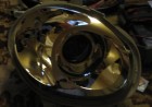
Step 3: Access and Remove Projector Assembly
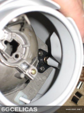
With the glass removed, locate the two screws securing the projector housing. Before attempting removal, detach the ball joint connection from the black plastic adjustment bracket. Remove the projector by unscrewing it from the adjustment rods on the rear. This reveals the core issue: the RHD-optimized beam pattern that needs modification.
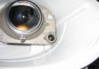
Step 4: Disassemble Projector for Modification
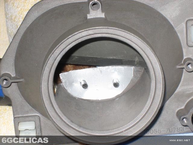
Remove the plastic piece and ball joint from the housing, then reattach them to the projector unit. Use side cutters to remove the ball joint completely. Open the projector by removing two screws from the back and two from the front. Inside, you'll see the cutoff shield - this angled piece is what creates the wrong beam pattern for LHD use.
Step 5: Fabricate New LHD Cutoff Shield
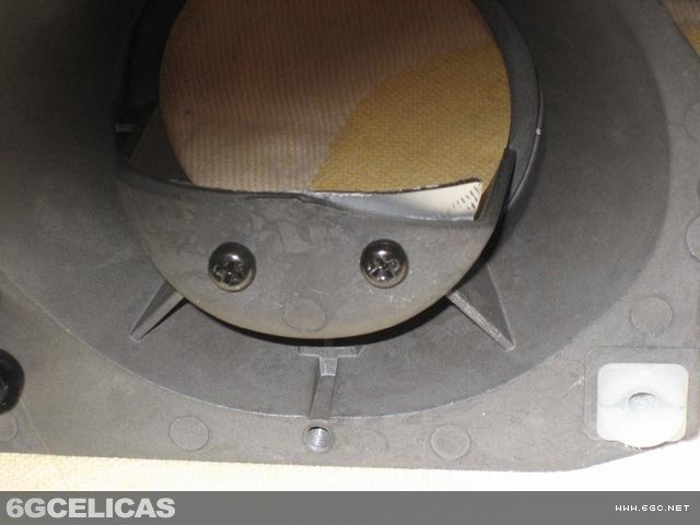
The critical modification: fabricate a new cutoff shield from 1mm sheet metal. The original RHD shield has an incorrect angle - create a new piece that is either completely horizontal or angled slightly upward. This redirects the light beam to provide proper illumination for driving on the right side of the road. Precision is crucial for optimal beam pattern.
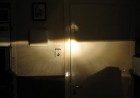
Step 6: Test Beam Pattern
Before final assembly, test your modification by temporarily reassembling just the projector housing (metal parts only). Connect a 12V transformer to power the projector and aim it at a wall to check the beam pattern. The cutoff should now be proper for LHD use. If unsatisfactory, fabricate another shield until the pattern is correct.
Step 7: Clean All Adhesive Residue
Most time-consuming step: Remove all old adhesive from both glass and plastic housing components. Soak parts in paint thinner for 10-minute intervals in a large container, then scrub with a brush to remove softened adhesive. Repeat this process multiple times until all surfaces are completely clean. This step is essential for proper reassembly.
Step 8: Final Assembly and Testing
Reassemble the projector with your modified cutoff shield, ensuring the ball joint is properly seated for adjustment capability. Carefully reassemble the headlight housing using appropriate sealant to maintain weather resistance. Test all functions including low beam, high beam, and adjustment mechanisms before installation in vehicle.
Expected Results
The completed modification transforms your JDM projectors from poorly performing headlights into properly optimized lighting for US roads. You'll experience dramatically improved visibility with correct beam patterns that illuminate the road surface where needed without blinding oncoming traffic. The modification maintains all original adjustment functionality while providing the safety and performance benefits that make projector headlights worthwhile.
👥 Safety Enhancement: Eliminates glare for oncoming drivers
⚖️ Legal Compliance: Meets DOT beam pattern requirements
🔧 Full Functionality: Maintains all original adjustment capabilities
Additional Reference
💡 Pro Tips
- Shield Fabrication: Use precise measurements and test multiple times - getting the cutoff angle perfect is critical for optimal beam pattern.
- Ventilation Safety: Work with paint thinner in a well-ventilated area or outdoors - fumes can be dangerous in enclosed spaces.
- Ball Joint Care: Handle adjustment mechanisms carefully - replacement parts for JDM projectors can be difficult to source.
- Testing Procedure: Test beam pattern on a flat wall at proper headlight height before final installation in vehicle.
- Documentation: Take photos during disassembly to ensure correct reassembly of all components.